Manual Cooling Fan Control
Updated July 31, 2000.
Some people have expressed interest in being able to either manually control their engine cooling fans, or have the cooling fans run at all times. On this page, I'll try to explain how to do it. Feel free to email me at slin01@mail.orion.org if anything is unclear.
Theory and Operation
The cooling fans in all W-body cars are driven by electric motors. Some
cars have one fan, but most have two, a primary and a secondary fan. Normally,
the ECM controls the fans and tells them when to turn on. The ECM uses inputs
from an engine temperature sensor and fan request lines to determine whether
one or both fans should come on. The ECM controls the fans by grounding the
coil on one or both relays. When the coil on a relay is grounded, it turns on
and switches on the appropriate fan. In order to manually control the fans,
what must be done, is to ground the relay coil. When the car is switched on,
one terminal of the relay coil is +12V (or hot at all times). The other terminal
is open. Ground that terminal, and the relay will switch on. You can add a switch
between that terminal and ground in order to manually control the fan.
How To Do It
Precautionary Testing. First, you will need to find the OPEN end of the relay coil (the end that is 0V, and NOT +12V). This is very important, because you'll blow a fuse if you accidentally ground the hot side of the coil. Here's how to do it:
|
Fig. 1 - Checking the terminals in the
Primary Fan relay socket. Notice the voltmeter reads close to +12V. That
means this is the HOT side.
|
Fig. 2 - Checking the terminals in the
Secondary Fan relay socket.
|
If you want to, you can just hope your car is wired the same as my Cutlass and not bother doing all the above testing. GM is usually pretty consistent, but sometimes the wiring varies. On my Cutlass, the terminal that's HOT is #85, so we need to ground #86. It's the same for both fan relays. If you ground the wrong side, you'll blow a fuse. The above procedure is just to make extra sure you do it right the first time.
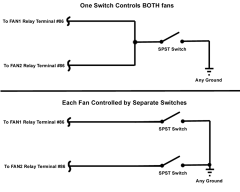
The Actual Modification. Okay, now we're ready to do the actual wiring.
|
Fig. 3 - Wrap a wire around the appropriate
terminal (#86 on my car).
|
 |
|
Fig. 4 - Here are a couple wiring examples.
|
Now you should be all finished. Test it out by turning the ignition on, and turning on your manual fan switch. The fan should be running. If it isn't, double check your wiring and make sure you wrapped your wire on the correct relay terminal. If you wrapped the wire on the wrong relay terminal, you may have blown the ALT fuse. Make sure you have a good ground and a good connection. If your fan(s) still won't come on, make sure the fan motors are good.
|
Fig. 5 - A quick example
|
I have quickly wired this up as shown in Fig. 5 and verified that it works fine. I didn't use a switch, I just grounded the black wire that I attached to relay terminal #86 to the engine using the white alligator clip. This does indeed work fine, although I just rigged it up temporarily for demonstration purposes.
Other Solutions...
There are other ways to implement manually controlled fans. If you want
a more permanent solution, you can actually tap into the wire(s) that feed the
relay coils using wire taps or splice right into it. The wires you'd need to
tap into is DK GRN-WHT for the primary cooling fan, and DK BLU-WHT for the secondary
cooling fan. You can then ground them or connect them to ground via switches
similar to the method I've explained. I chose to just attach the wire to the
relay itself because it's, a) easier, and b) very easily reversible. If you
solder the wire to the relay terminal itself, that would probably be more reliable
than wire taps. I chose to ground the relay coil instead of shorting across
the relay with a switch because, a) it won't hurt the ECM (as the ECM uses open-collector
outputs to the fan relays), b) the fan will switch off with ignition off, and
c) you aren't dealing with high current, so you can get by with small gauge
wire which is easier to conceal.
Copyright ©2000 The W-Body Page